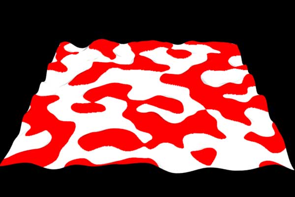
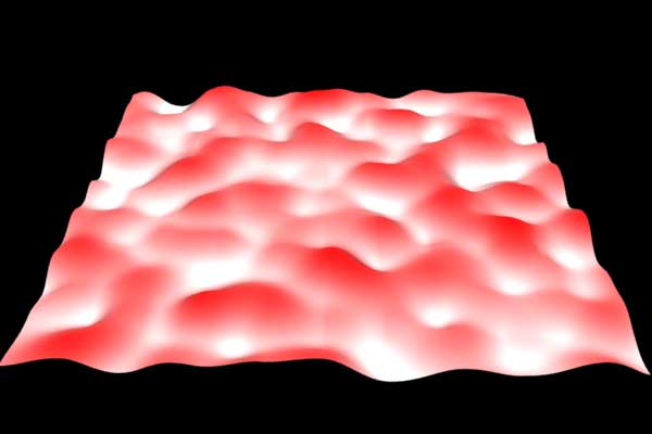
In this challenge we were asked to change the color of a polygonal object based on the displacement of the object. Renderman has the ability to pass information about a displacement shader to a surface shader by the use of : output varying float Use of this allows the displacement or "hump" value to be parsed to the surface shader which then can be used to control where color should be placed on the displacement. To show this I used a basic noise based displacement and parsed the information to the surface shader using the above float command. What I got was this:
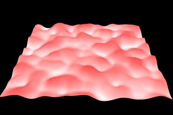
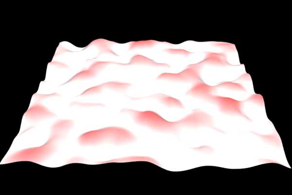
Essentially, everything that is over 50% of displacement values coming into the surface shader is colored red. This is a basic representation of the shader working, but there is aliasing at the point where the color changes. To remedy this, I resorted to using "smoothstep" to ramp between the colors. I also included in the surface shader the ability to control the amount of "smoothing" or "ramping" between the two colors. This is what the shader returned with different values for "smoothing":
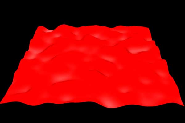
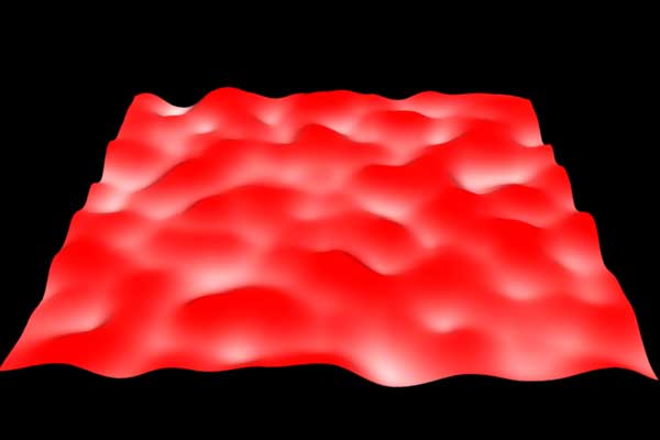
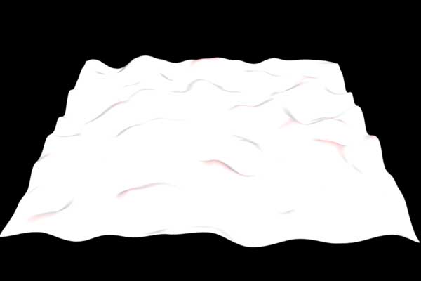
As you can see, by controlling the amount of "ramp" you get quite different effects happening to the shader. With this in hand, I was also to control the point at which the ramp is applied to the displacement. I then was able to move the "ramp" up or down the displacement. This is the effect of moving the ramp based on the percentage of the hump value:
I left the "ramp" value low so to show the movement of the linepoint up the displacement. I made a couple of movies of both of these ideas to be able to better show what is happening as the values are changing.
click for displacement shader code
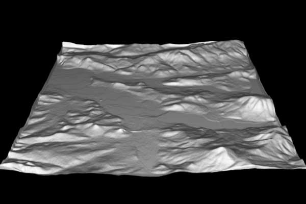
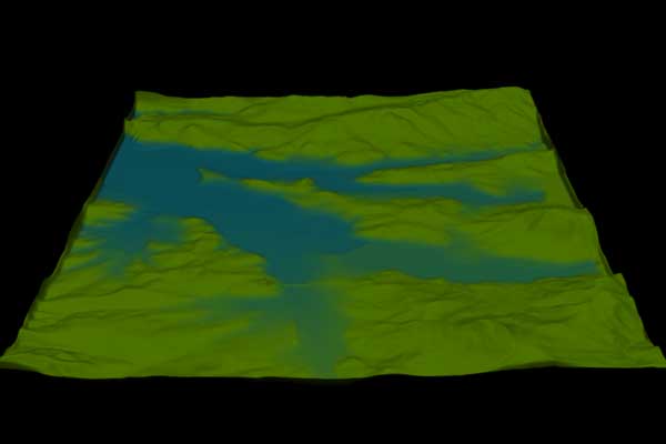
So I decided to take this idea a bit further and attempt to use a texture map for displacement and then get a gradient between two colors from this. I first looked for a decent texture map. I was able to find some DEM (Digital Elevation Maps) online and with the help of James Van Allen I converted the DEMs to TIFFs. Taking the TIFF file into Photoshop I "squared" the map to 256 x 256. Once having a workable TIFF image, I converted it into a TX so that renderman could recognize the map. Instead of using a noise function in the displacement shader, I used texture function to read the displacement and parse the information to the surface shader. This is the displacement I ended up with:
I chose this DEM for two reasons: 1. It has a great delineation between the lower part (which is a lake) and the surrounding mountians 2. This is the DEM of Lowell, OR, which is the area where my parents live. So, with this displacement, I used the parsed information and read it in the basic surface shader above to get the correct delineation between the lake and the mountains. With some "tweeking" of the ramp and linepoint values I was able to get this image:
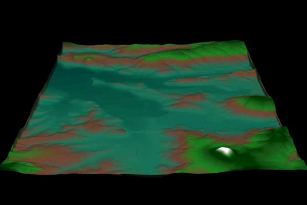
Even though this came out pretty well, I wasn't happy with just the two colors. I then turned to the use of "spline" within the surface shader to get more color gradients within the image. I found that "spline" needed in and out points to control the "curve" of the colors up through the the displacement. I also found that spline is difficult to control, but this is the image I was able to get using "spline" with 8 separate color values.
As you can see from the image, the "spline" still needs to be "tweeked" to get a better representation of where the colors really should be. All in all, I am satified with the results. click for Lowell displacement code
|